- PROFESSIONAL MECHANICAL EQUIPMENT COMPONENT SUPPLIER -

Views: 0 Author: Site Editor Publish Time: 2026-10-22 Origin: Site

Are your machined parts failing rigorous quality tests? Walk onto any busy shop floor, and you will likely see the reality: even microscopic deviations can trigger a cascade of scrapped components. This leads to bloated budgets and severe production delays. Achieving exact specifications requires much more than simply loading a billet into a chuck. It demands a flawlessly orchestrated manufacturing environment.
For cylindrical and symmetrical components, optimized Lathe Machining stands as the definitive solution to these costly bottlenecks. In this comprehensive guide, we will explore how to fine-tune every phase of the turning process. From initial design geometry to final metrology, we will show you how to ensure unparalleled precision and repeatability on the production floor.
In modern manufacturing, achieving the exact specifications required by advanced industries is a rigorously unforgiving process. Sectors like aerospace, automotive, medical, and heavy equipment manufacturing demand components that perform flawlessly under extreme stress. When executed correctly, professional turning operations provide the unparalleled accuracy required to meet these stringent industrial standards.
High-precision turning is not merely about shaping a piece of metal. It is about controlling physical variables at a microscopic level. In this context, precision is defined by three primary metrics. First is the dimensional tolerance. This often requires maintaining measurements within ±0.0001 inches, roughly a fraction of the width of a human hair. Second is the surface finish, typically measured in micro-inches and denoted as Ra. The ultimate goal here is to achieve a mirror-like smoothness that drastically reduces friction and mechanical wear. Third is concentricity and runout. This ensures that a cylindrical part rotates perfectly on its true axis without any wobble. Achieving these strict metrics requires a holistic approach that perfectly synchronizes the machine tool, the cutting insert, the raw material, and the operator expertise.
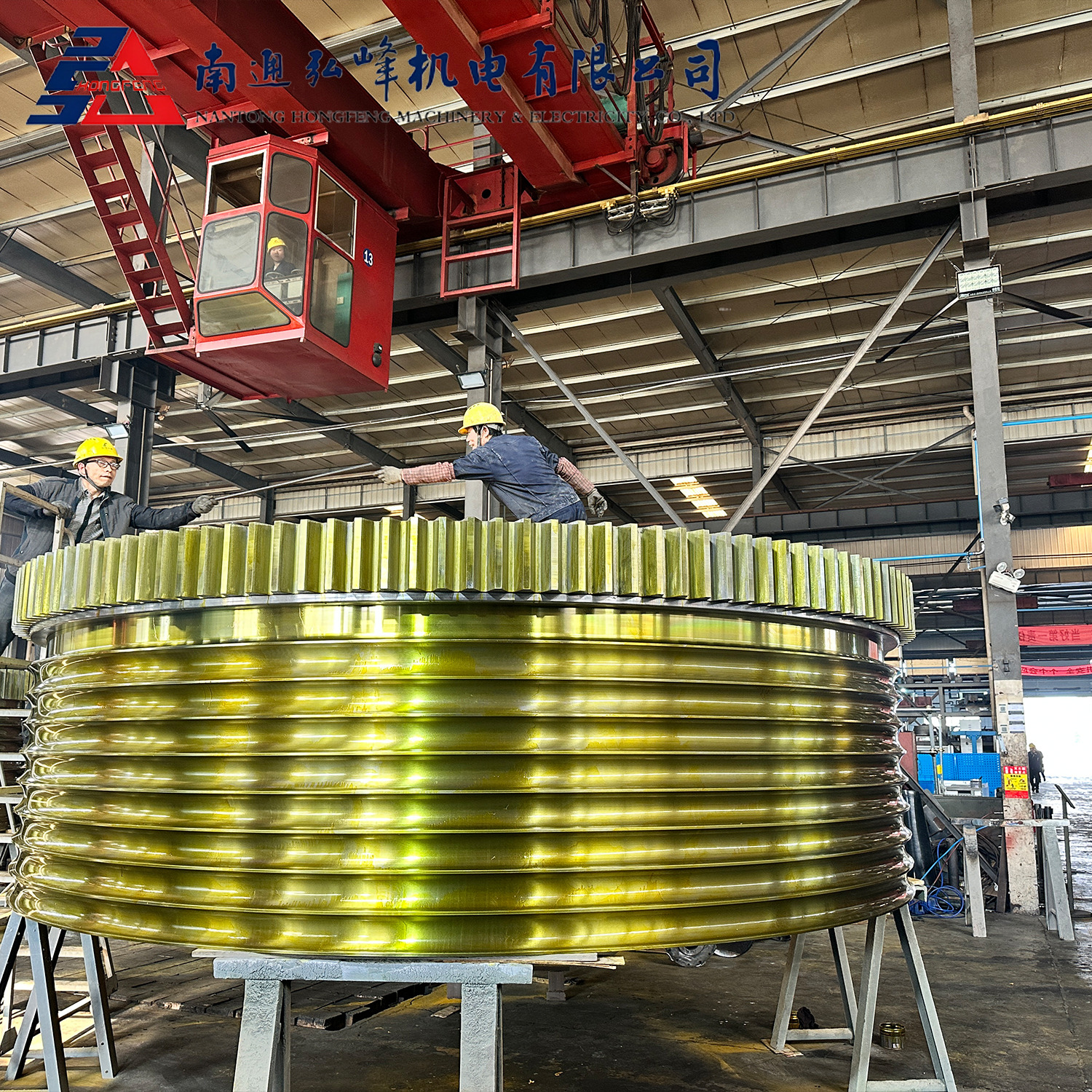
Precision turning forms the mechanical foundation of complex systems. These parts are heavily utilized as hydraulic valve spools, aerospace fasteners, titanium medical bone screws, and specialized industrial rollers. Specifically, in heavy-duty industrial applications, components such as cable equipment traction wheels require absolute concentricity and perfect dynamic balance. This guarantees the smooth operation of wire drawing and cable stranding machinery. Any deviation in these precision lathed components can lead to catastrophic system-wide failures. This highlights exactly why optimized lathe operations are absolutely essential.
The foundation of high-precision manufacturing is established long before a raw steel blank is ever loaded into the machine. Design for Manufacturability, commonly known as DFM, is an engineering philosophy focused on simplifying part design. The goal is to reduce machining complexity, minimize lengthy setup times, and eliminate potential sources of human error.
Picture a machinist pausing the cycle to unchuck a half-finished titanium shaft. They flip it by hand and re-clamp it to machine the back side. That single manual intervention introduces microscopic alignment shifts. This phenomenon, known as tolerance stacking, can quickly push a high-precision part completely out of specification. To combat this, engineers should design components so that the maximum number of features can be machined in a single, uninterrupted operation. By consciously avoiding overly complex internal geometries or features that force secondary milling setups, designers can significantly improve the final accuracy of the lathed component.
Inconsistent design elements force machinists to perform multiple tool changes. This inherently increases cycle time and the potential for dimensional variances. Standardizing these design parameters ensures that standard cutting tools can remain engaged throughout the process. Furthermore, maintaining a uniform wall thickness is absolutely critical. Thin, delicate walls are highly susceptible to chatter, a form of destructive vibration. Under the immense pressure of the cutting tool or the crushing clamping force of the chuck jaws, these thin walls will warp and deform.
| Design Feature | Optimization Guideline for Lathe Machining | Objective |
|---|---|---|
| Internal Corners | Specify standard tool nose radii, such as 0.015 or 0.031 inches. | Prevents the need for custom tooling and reduces structural stress concentrations. |
| Hole Depth | Limit depth-to-diameter ratio to 4:1 where possible. | Avoids drill wandering and ensures accurate, repeatable concentricity. |
| Wall Thickness | Maintain a minimum wall thickness of 0.020 inches, depending on the material. | Prevents part deformation from chuck clamping and tool pressure. |
| Undercuts | Standardize undercut widths and depths across the part. | Allows a single grooving tool to machine all undercuts in one rapid pass. |
Material selection directly dictates the machining parameters, tool selection, and the ultimate precision of the finished component. Different alloys and polymers exhibit wildly distinct physical behaviors when subjected to the sheer forces and blistering temperatures of the cutting process.
The machinability rating of a material dictates how cleanly it can be cut while maintaining a superior surface finish. Soft metals like 6061 aluminum are highly machinable, allowing for aggressive cutting speeds and excellent finishes. However, they are notoriously prone to sticky chip buildup on the cutting edge. In contrast, machining high-carbon steel or stainless steel demands lower speeds and specific carbide insert geometries to penetrate the tough exterior. Titanium poses unique thermal challenges due to its low thermal conductivity. Instead of the heat dissipating into the chips, it builds up rapidly at the cutting edge. Moving beyond metals, plastics like Delrin or PEEK require extremely sharp tools. Imagine machining a critical PEEK medical implant. If the feed rate drops even slightly, the material gums up around the insert, instantly melting and ruining the batch.
Thermal dynamics dictate the success or failure of high-precision lathe machining. As the cutting tool aggressively shears away material, significant thermal energy is generated. It is a basic rule of physics that metals expand when heated. If an operator turns a part to a specific micro-inch diameter while the material is still hot, the part will inevitably shrink as it cools. This results in an undersized, scrapped component. Managing this thermal expansion requires a deep understanding of the specific alloy coefficient of thermal expansion. Machinists mitigate this risk by strictly controlling ambient shop temperatures. They utilize heavy roughing passes to remove bulk material quickly, and allow the part to stabilize thermally before taking the final, ultra-precise finishing pass.
The physical act of shearing metal is governed by strict mathematical and physical principles. Optimizing a turning center requires precise, intentional control over three main parameters: Spindle Speed, Feed Rate, and Depth of Cut. Getting these wrong means immediate tool failure or out-of-spec parts.
In lathe operations, the cutting speed is typically calculated in Surface Feet per Minute, which is then mathematically converted to RPM based on the exact diameter of the workpiece. Selecting the correct RPM is non-negotiable. If the speed is set too high for a specific hardened steel, the extreme friction will cause rapid, catastrophic tool wear. This leads directly to dimensional drift. Conversely, if the RPM is too low, the material tends to tear rather than shear cleanly. This results in a rough, visually unacceptable surface and a built-up edge on the tool insert. Modern CNC lathes utilize Constant Surface Speed programming. This intelligent feature automatically increases the spindle RPM as the tool moves closer to the center axis of the part, ensuring a perfectly consistent cutting velocity across varying diameters.
Feed rate dictates the surface roughness of the component. A slower feed rate generally produces a smoother, glass-like finish. However, it significantly increases cycle time and can cause the tool to rub rather than cut, inducing excess heat. Consequently, the depth of cut must be perfectly balanced with the feed rate. Standard industry practice involves taking heavy roughing passes with a large depth of cut and a moderate feed rate to evacuate material efficiently. This is immediately followed by a very light, delicate finishing pass with a fine feed rate. This two-step process is how machinists hit exact dimensional tolerances and achieve the desired surface finish.
Achieving high-precision tolerances is not solely dependent on the machine software programming. The physical hardware executing the cut plays a foundational role. Upgrading your toolcrib for high-end operations is a direct pathway to optimizing the entire manufacturing process.
High-speed steel is rarely utilized in modern high-precision production environments. Today, advanced coated carbide inserts are the industry standard. These inserts feature specialized chip-breaking geometries and chemical coatings like Titanium Nitride that actively resist heat and prolong tool life. For machining hardened steels or cast iron, ceramic inserts are often deployed because they can withstand extreme, glowing temperatures. When tackling highly abrasive non-ferrous materials, Polycrystalline Diamond inserts are the ultimate choice. These diamond tools maintain a razor-sharp edge over thousands of production cycles, which is critical for maintaining tight tolerances without requiring constant, manual tool offsets.
During the cutting process, coolant serves two indispensable functions: mechanical lubrication and strict temperature control. In precision turning, standard low-pressure flood coolant is often vastly insufficient. Upgrading to high-pressure coolant systems provides game-changing advantages. Delivering cutting fluid directly at the cutting zone at 1,000 PSI or higher literally shatters the metal chips into small, manageable pieces. This prevents the chips from wrapping dangerously around the workpiece or being re-cut by the tool. Furthermore, the high-pressure fluid effectively extracts heat from the cutting zone, keeping the workpiece dimensionally stable and wholly preventing thermal deformation.
The evolution of CNC technology has transformed the traditional two-axis lathe into a comprehensive, multi-functional manufacturing center. Leveraging these advanced technologies is absolutely essential for optimizing the mass production of complex, multi-featured components.
Looking at current industry trends, the landscape of component manufacturing is experiencing a massive shift toward smart integration. Recent market data indicates a surge in the adoption of IoT-enabled digital twins and AI-driven thermal compensation within CNC turning centers. Rather than relying solely on a machinist intuition, modern facilities leverage machine learning algorithms to predict tool degradation before it happens. This data-first approach is revolutionizing how manufacturers handle exotic alloys. It drastically cuts down scrap rates and pushes the boundaries of what is dimensionally possible.
Historically, if a cylindrical part required a milled flat surface or off-center cross-holes, it had to be physically removed from the lathe and set up on a separate milling machine. This secondary setup inherently introduced alignment inaccuracies. Modern multi-axis CNC lathes are equipped with live tooling and Y-axis capabilities to solve this. Combined with a C-axis spindle that can precisely index and lock the workpiece at specific angles, these machines can perform complex milling, drilling, and tapping operations in a single setup. This done-in-one approach drastically reduces cycle times and entirely eliminates tolerance stacking.
Human error in setting tool offsets is a notoriously common cause of precision failures. Advanced CNC lathes heavily mitigate this through automation and sophisticated in-machine probing systems. Automated tool presetters physically measure the exact length and radius of the cutting tool inside the machine, updating the CNC control instantly. Similarly, spindle-mounted tactile probes can measure the workpiece before, during, and after the machining cycle. If a roughing pass leaves slightly too much material due to microscopic tool wear, the in-machine probe detects the variance. It then automatically adjusts the finishing tool offset. This closed-loop feedback system guarantees that the final part meets exact dimensional specifications.
Optimization does not end the moment the spindle stops turning. High-precision manufacturing requires rigorous, objective verification to ensure that the final physical component matches the engineering CAD drawings perfectly. When executing a complex Lathe Machining service, quality control must be an active, continuous process.
Advanced manufacturing facilities utilize real-time process monitoring to ensure batch consistency. Spindle load monitors continuously track the amount of electrical power the machine is using to cut the material. A sudden spike in spindle load is a clear indicator that the tool is wearing out or chipping. Additionally, vibration analysis sensors can detect microscopic chatter long before it becomes visible to the naked eye on the part surface. By catching these mechanical anomalies in real-time, operators can halt the machine and replace the tool before a high-value component is scrapped.
Once the part is safely removed from the chuck, it must undergo strict metrology testing in a climate-controlled lab. Coordinate Measuring Machines utilize highly sensitive, ruby-tipped probes to meticulously measure the complex geometries, concentricity, and dimensional accuracy of the part down to the micron level. These precise measurements are cross-referenced directly against the original 3D model. Additionally, profilometers are utilized to drag a microscopic diamond stylus across the machined surface to quantify the surface roughness. Only parts that pass these objective, data-driven inspections can be certified and shipped.
Achieving the level of precision detailed in this guide requires immense capital investment in state-of-the-art machinery, specialized tooling, metrology equipment, and highly skilled personnel. For many OEMs and product developers, attempting to manage this intense learning curve internally is simply not cost-effective.
Outsourcing to a dedicated manufacturing partner ensures immediate access to the latest CNC technologies and seasoned machinists. These experts intimately understand the nuances of thermal dynamics and material behavior. When evaluating a potential manufacturing partner, it is crucial to look for objective indicators of quality. ISO 9001 certifications guarantee strict adherence to standardized quality management systems. Furthermore, examining their facility for rigid, multi-axis lathes and climate-controlled inspection rooms will provide the confidence needed in their ability to hold tight tolerances consistently.
Not all machining shops are equipped to handle every type of component. Finding a partner with niche expertise relevant to your specific industry provides a massive strategic advantage. For instance, heavy-duty industrial rollers require highly specific workholding strategies to prevent distortion during aggressive machining. When processing cable equipment traction wheels, engineers must ensure concentricity is held within 0.01mm, dynamic balancing meets G2.5 grades, and the surface finish achieves Ra 0.8 to prevent any damage to the cable during operation. Partnering with a facility like Hongfeng Machine ensures that the manufacturer already intimately understands these critical, real-world requirements. This specialized experience translates directly to faster turnaround times, significantly lower scrap rates, and a reliable return on investment. Explore our custom turning solutions to bring your most demanding components to life flawlessly.
Conclusion
Optimizing lathe machining is a holistic endeavor that requires smart, intentional design and precise control over cutting physics. Advanced tooling, high-pressure coolant strategies, and strict, data-driven quality checks are vital to success. Ultimately, high-precision components are what build reliable, long-lasting industrial machinery. Cutting corners during the machining phase will inevitably lead to unexpected product failures in the field. Partner with seasoned experts for your next precision manufacturing project, and ensure your production line never stops moving.
Modern CNC lathes can routinely achieve dimensional tolerances as tight as ±0.0001 inches, which is approximately 2.5 microns. However, achieving this maximum precision is highly dependent on several interconnected factors. The structural rigidity of the machine tool, the machinability of the chosen alloy, and strict environmental temperature control within the facility are all absolutely required to prevent thermal expansion from distorting these micro-measurements.
The primary difference lies in the kinematics of the cutting process itself. In turning operations, the workpiece is rapidly rotated against a stationary cutting tool, making it the optimal, most accurate method for creating perfectly cylindrical or symmetrical parts. Conversely, milling involves securing a stationary workpiece to a table while a multi-point cutting tool rotates against it, which is far better suited for flat surfaces, deep slots, or irregular block-like geometries.
Cost reduction begins early in the engineering phase through Design for Manufacturability. You can significantly lower production costs by standardizing internal hole sizes to match common drill bits, avoiding excessively deep cavities, and removing unnecessarily tight tolerances on non-critical dimensions. Furthermore, designing components that can be entirely machined in a single setup eliminates the costly labor and alignment risks associated with moving parts between different machines.
Rotation speed dictates the surface cutting speed at the point of contact. If the RPM is calculated incorrectly for the specific material being cut, the physics of the operation completely break down. Excessive speeds generate uncontrolled, extreme heat, leading to rapid tool degradation and thermal distortion of the part. Conversely, speeds that are too slow cause the material to tear rather than shear cleanly, resulting in an unacceptable surface finish and increased mechanical stress on the spindle.
Material hardness directly impacts the allowable cutting speed and feed rate. Harder materials, such as heat-treated tool steels or titanium alloys, require significantly slower spindle speeds and lighter depths of cut to prevent rapid tool failure. This inherently extends the machining cycle time. In contrast, softer materials like aluminum can be machined at extremely high speeds, drastically reducing the overall cycle time per part.
For cable equipment traction wheels, an ideal surface finish typically falls around Ra 0.8 to Ra 1.6 micrometers. A surface that is too rough will cause excessive friction and premature wear on the wire or cable being drawn. Conversely, an overly polished surface might lack the necessary friction to grip the cable effectively. Achieving this specific Ra value requires a perfect balance of finishing feed rates, sharp carbide inserts, and high-pressure coolant.